

Intrusive Soldering (Pin-In-Paste)
How CircuitHub performs intrusive soldering (pin-in-paste) for hybrid components, and what to expect from the resulting solder joints per IPC-A-610.
For many years there were 2 types of components. Surface Mount components and Thru-Hole components. But lately, there are a growing number of Hybrid components, which are populated using a Surface Mount process but really have Thru-Hole elements to them.
To solder these types of components, we use Intrusive Soldering, sometimes called pin-in-paste. Our experience with these types of components is that an intrusive soldering process can result in a stronger connection than a standard thru-hole soldering method. It just looks really weird at first. But once you understand how it's being accomplished, you'll find that the connection is actually very strong and reliable.
Let's start out by showing the specifications for a thru-hole solder joint according to IPC-A-610.
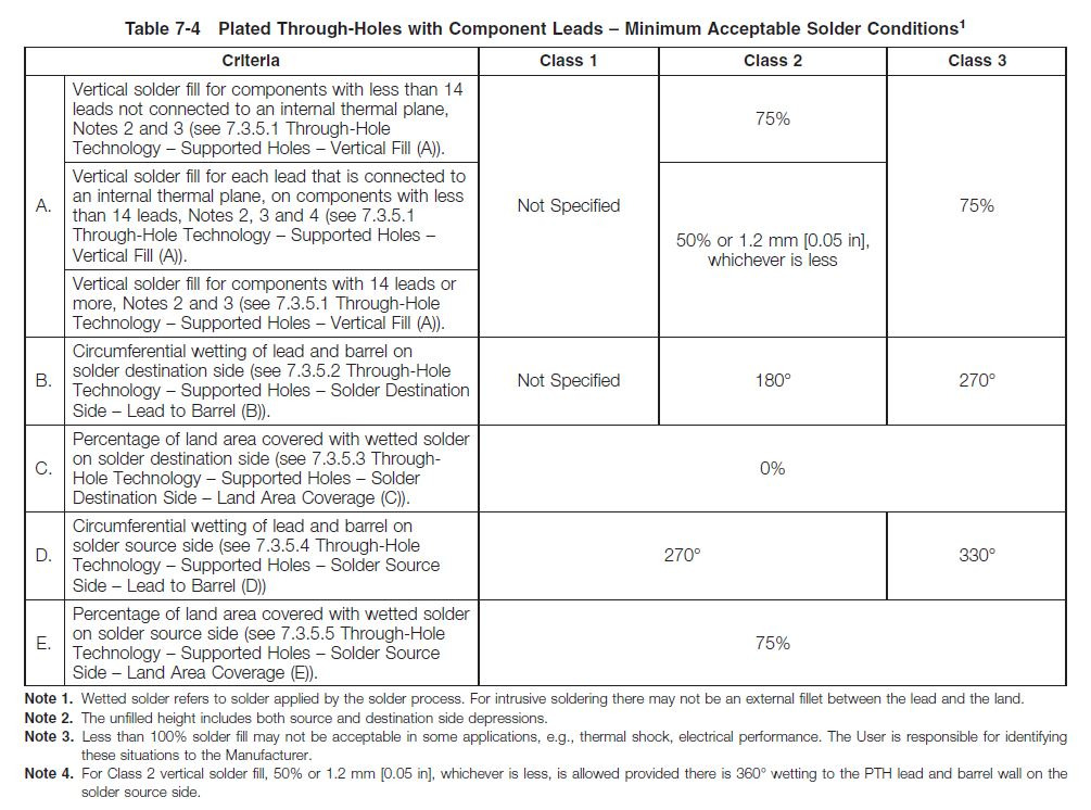
Notice within the name of the table there's a Note 1 at the end, which references this sentence at the bottom of the table. "Note 1: Wetted solder refers to solder applied by the solder process. For intrusive soldering there may not be an external filet between the lead and the land."
With this in mind, let's look at how Intrusive Soldering works and what you should expect from an Intrusive Soldering process.
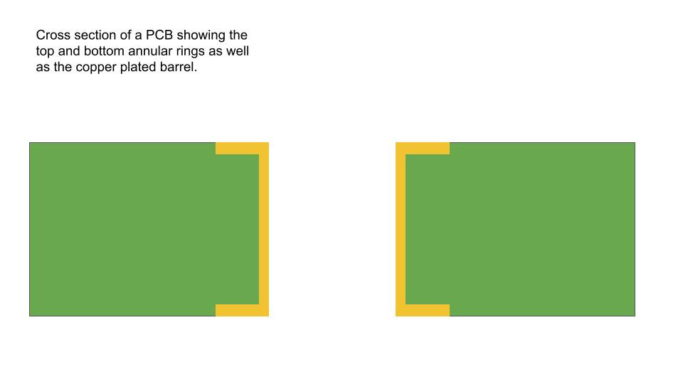
Here's a cross section view of a PCB before any soldering is performed.
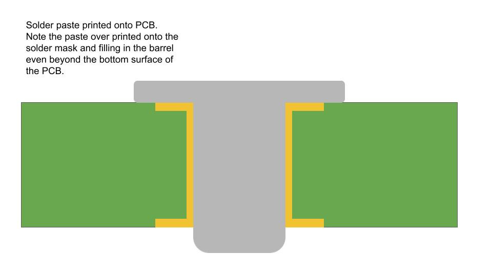
We start by applying as much solder paste to the location as we can. We will typically overprint the solder paste onto the solder mask and use multiple strokes of the squeegee blades in order to pack the solder into the hole.
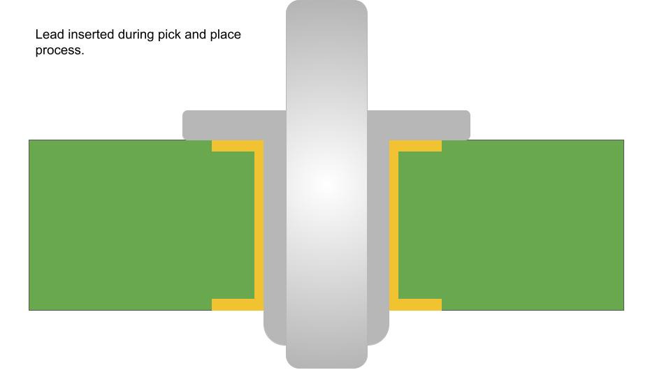
The PCB will then transfer into our pick and place machine where the component will be populated and its leads will be inserted into the board.
Then it's on to the reflow oven where the solder joint is made. It's important to point out here that solder paste is only about 50% metal by volume. The rest is flux. This means that even though we've filled the barrel with solder paste, once the paste is melted in the reflow oven and the flux is consumed, we'll be left with only about 50% of the same volume after it comes out of the reflow oven. The results will look something like this.
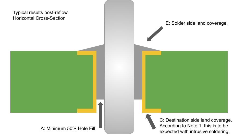
Referring back to Table 7-4 the image above points out rows A, C, and E and what they might look like with Intrusive Soldering.
Row A defines the minimum hole fill. It's very likely that we will achieve 50% or greater hole fill with this soldering process.
Row C defines the land coverage on the destination side (the side where no solder is applied directly). 0% coverage is required here and typically very little will be found with an intrusive soldering process.
Row E defines the solder side land coverage. With intrusive soldering you will almost always get 100% coverage, but you typically won't be able to see it. This is because the component body itself is covering the view of this solder joint.
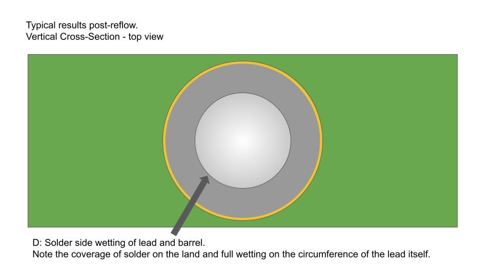
Referring back to Table 7-4 the image above points out row D and what it might look like with Intrusive Soldering.
Row D defines the solder side wetting of the lead and the barrel. With intrusive soldering you will almost always get 100% lead and barrel wetting on the solder side, but just like with land coverage, you typically won't be able to see it because the component body itself is covering the view of this solder joint.
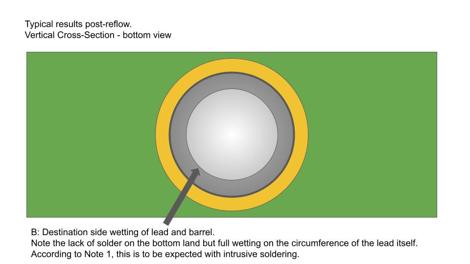
Referring back to Table 7-4 the image above points out row B and what it might look like with Intrusive Soldering.
Row B defines the destination side wetting of the lead and barrel. With intrusive soldering you will almost always get 100% lead and barrel wetting on the destination side, but typically this wetting will be inside the barrel itself and difficult to see with the naked eye, and may require magnification.
CircuitHub processes components using this soldering process every single day, with great results. So if you've received your boards and they look a little bit different than expected, rest assured that those solder joints are strong and reliable and conform to the standards set by the committee that wrote the IPC-A-610 criteria.