

Fusion 360 import guide
Export Gerber files and EAGLE-compatible board and schematic files from Fusion 360, and check which files CircuitHub needs to import your design.
CircuitHub imports Autodesk Fusion (formerly Fusion 360) electronics designs from two sets of files that you export from Fusion:
- The manufacturing files from the CAM Processor: Gerber X2 layers, drill files and a Gerber job file. These give us the copper, solder mask, paste, silkscreen, board outline and drill layers.
- The board and schematic in the legacy EAGLE format. These give us the bill of materials, footprints, part placements and the schematic symbols we use to check polarity.
You need both. Gerber files on their own cannot be imported, and Fusion's own design files (.fbrd, .fsch, .f3z) are not recognized.
Specifying part numbers
Which attribute names CircuitHub reads manufacturer part numbers from.
Supplying a BOM
Supplement the data from your design files with a CSV bill of materials.
Why we require schematics
How schematic data reduces the risk of manufacturing errors.
Before you upload
Save your design, then make all three exports below from that same saved version.
CircuitHub checks each part placement in the board file against the pads in your Gerber files, and the import fails if most of them do not line up, for example when the Gerbers come from an older version of the board. CircuitHub cannot tell when the board and schematic files come from different versions, so whenever you change the design, make all three exports again.
1. Export the manufacturing files
-
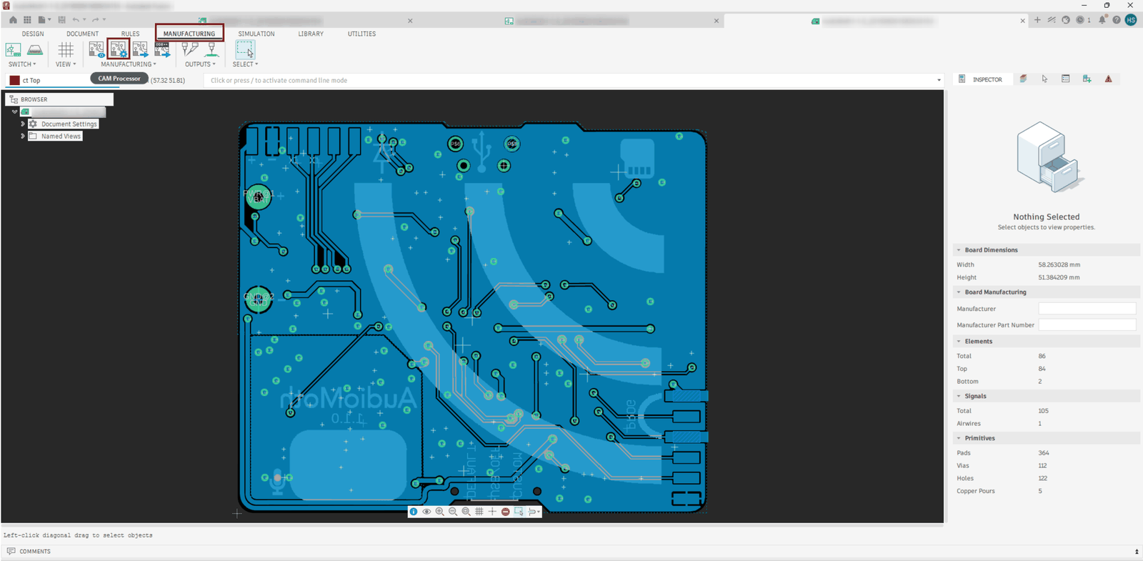
Open your board in Fusion. On the Manufacturing tab, choose CAM Processor.
-
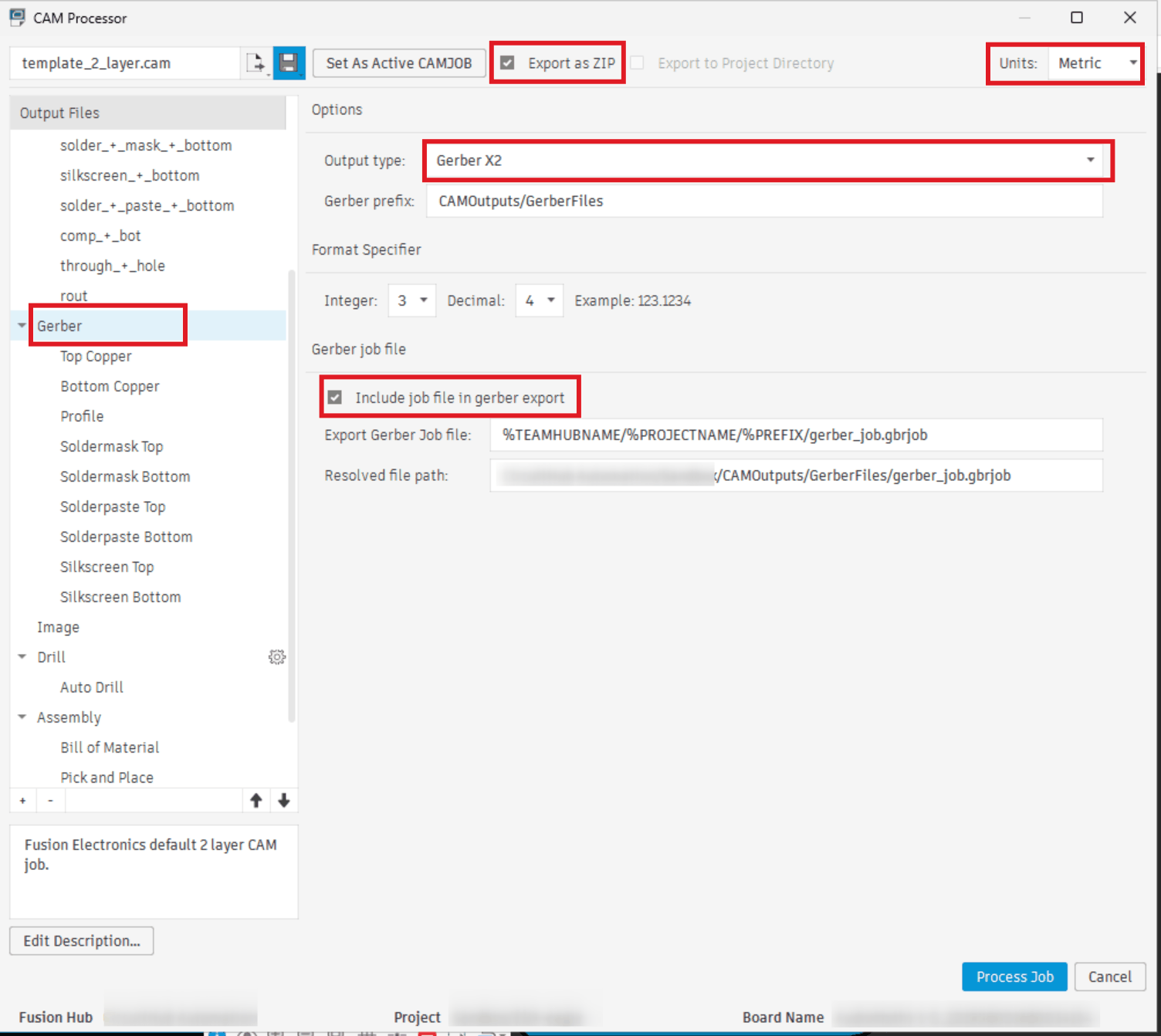
In the CAM Processor dialog, check that:
- Export as ZIP is selected.
- Units is set to Metric.
- In the Gerber section, Output type is set to Gerber X2.
- In the Gerber section, Include job file in gerber export is selected.
-
Choose Process Job and save the ZIP file.
Fusion's default CAM job also writes the drill file, drill_1_16.xln, into the ZIP. Keep it: CircuitHub needs at least one drill file that goes through the whole board. The assembly and ODB++ files in the ZIP are not used and do no harm.
2. Export the board file
-
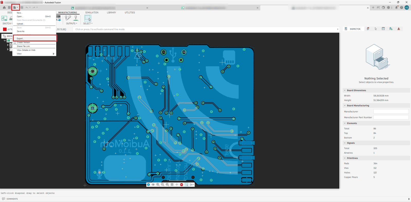
With the board open, open the File menu and choose Export….
-
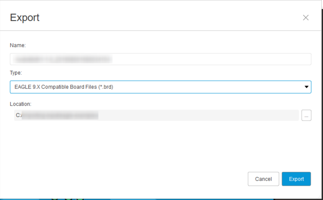
Set Type to EAGLE 9.X Compatible Board Files (*.brd) and choose Export.
3. Export the schematic file
-
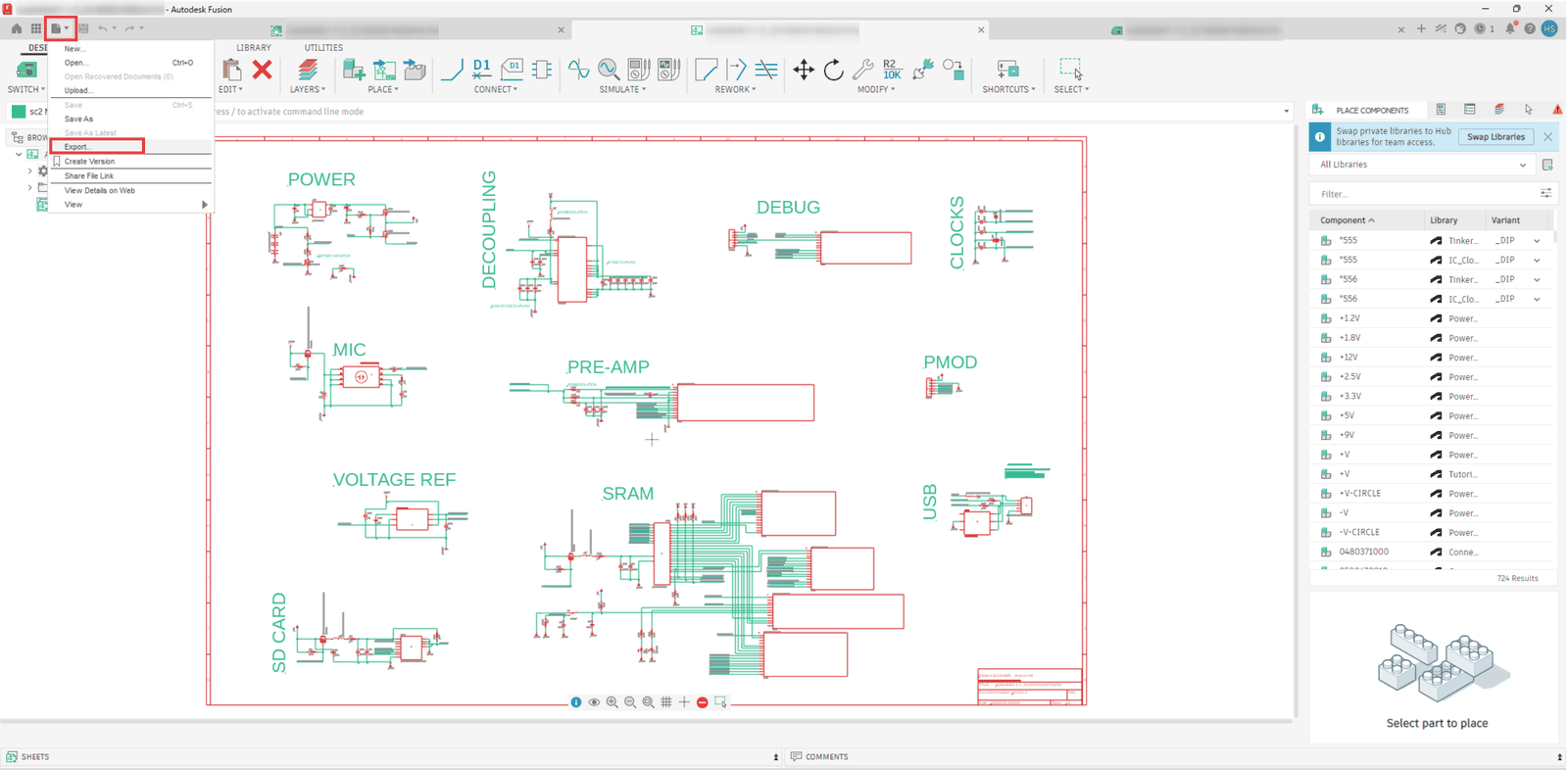
Switch to your schematic, open the File menu and choose Export….
-
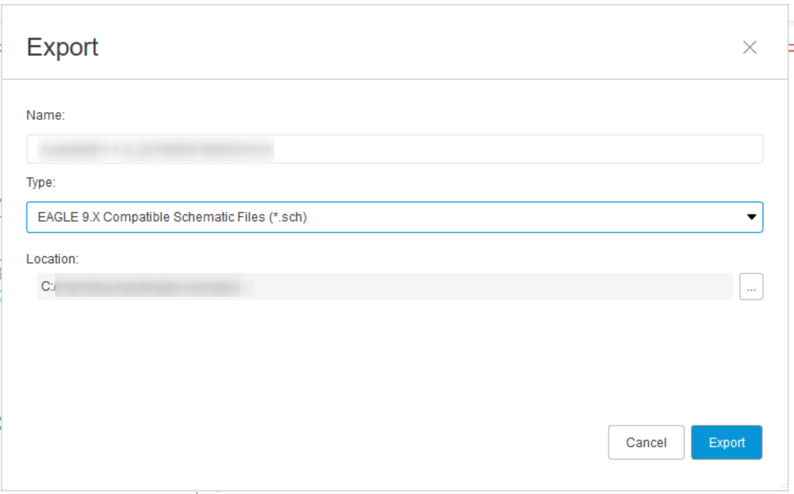
Set Type to EAGLE 9.X Compatible Schematic Files (*.sch) and choose Export.
Uploading
Upload the .brd file, the .sch file and the CAM Processor ZIP together. The upload page unpacks the ZIP for you; you can also upload the files inside it one by one.
The upload page treats these exports as an EAGLE project, so the board and schematic show as Board · Eagle and Schematic · Eagle.
The upload page marks drill_1_16.xln as plated holes through all layers and asks you to confirm this. Check that this matches your drill file: if it does, choose Confirm; if not, open the row's … menu and choose Edit drill details to change it.
If your board has blind or buried vias, Fusion also writes a drill file for each layer pair, such as drill_1_2.xln. Choose Set drill details on each one and give its layer span, counting copper layers from 1 at the top down to the bottom layer. These numbers can differ from those in the file name, where Fusion always numbers the bottom layer 16: on a four-layer board that uses Fusion layers 1, 2, 15 and 16, drill_2_15.xln spans layers 2 to 3. After the import, check the number of blind/buried layer sets in the board options on your project page.
Once every drill file is confirmed, the upload page shows Ready to import as an Eagle project.
Required files
- One board file, where the name ends in
.brd, exported as EAGLE 9.X compatible. - One schematic file, where the name ends in
.sch, exported as EAGLE 9.X compatible. - The Gerber files for every copper layer and exactly one board outline (
profile.gbr), together with the solder mask, paste and silkscreen layers that Fusion exports. - At least one drill file that goes through the whole board (
drill_1_16.xlnfrom the default CAM job).
Recommended
- The Gerber job file,
gerber_job.gbrjob. CircuitHub reads your board thickness from it and checks that it lists the same number of copper layers as your Gerber files. Only one job file is allowed.
Optional BOM
You can also upload a BOM in either .csv or .tsv that conforms to the supported format.
Where your data comes from
| Data | Source |
|---|---|
| Copper, solder mask, paste, silkscreen and board outline | The Gerber files. |
| Holes | The drill files. |
| Board thickness | The Gerber job file. |
| Parts, footprints and placements | The board file. |
| Values and descriptions | Both files, matched by reference designator. Where they differ, the schematic wins. |
| Manufacturer / distributor part numbers | The schematic file: part attributes, and attributes set on the device or technology in its library. |
| Symbols, used to check polarity | The schematic file. |
Parts that are in the schematic but not on the board are left out. Add manufacturer part numbers as attributes on the schematic parts, such as MPN or ManufacturerPartNumber; see Specifying part numbers in EDA tools.
CircuitHub does not read do-not-place (DNP) settings or assembly variants from Fusion designs. Mark those parts as DNP on CircuitHub after the import, or use the DNP column of a CSV BOM.
Single design
Only upload files from a single design at a time. Supplying files from different designs leads to ambiguities during import.
Older EAGLE files
The EAGLE 9.X compatible export is an XML file. Binary .brd and .sch files from EAGLE 5 and earlier are not supported; the upload page asks you to re-export them as XML.